Measurement on Flashlight
Sometimes it can be necessary to do some measurement on a flashlight or battery, this article shows how to do the most common electrical measurements. These measurements are possible on most lights, but not on all.
For some of these measurements I will use two multimeters, a very cheap on and a expensive one.
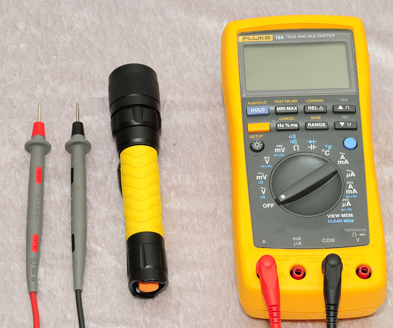
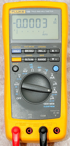
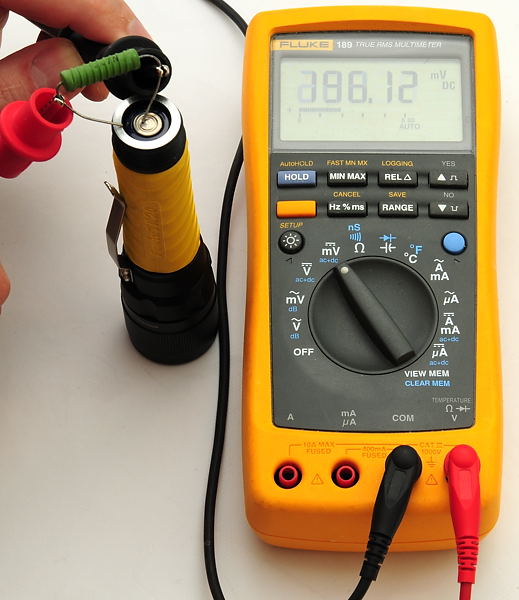
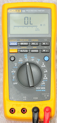
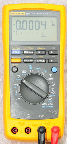
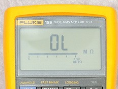
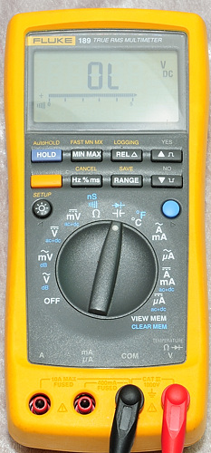
The expensive meter is a Fluke 189, it has lots of digits, autorange and a very high accuracy.
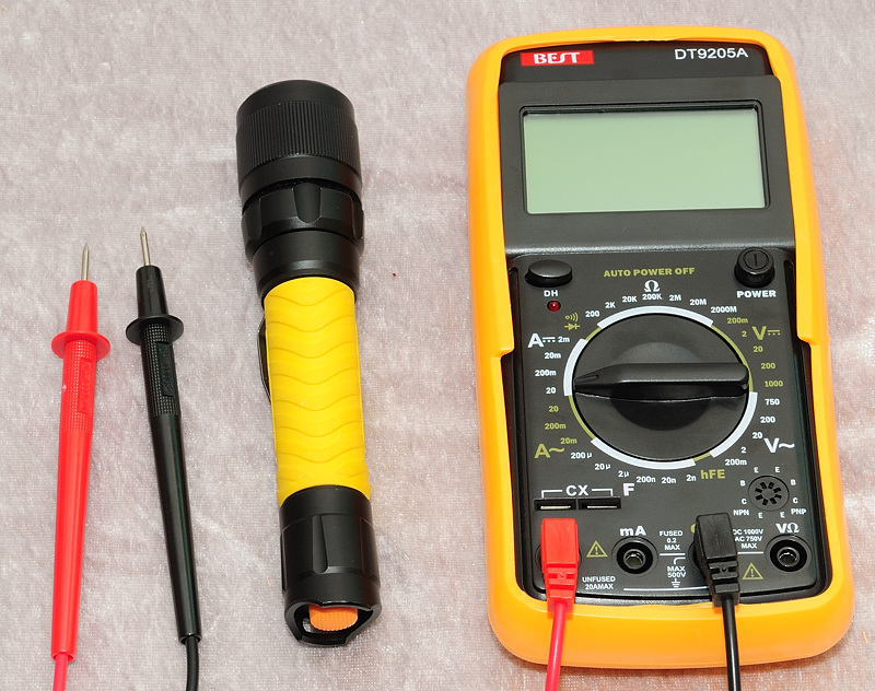
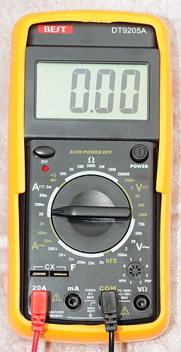
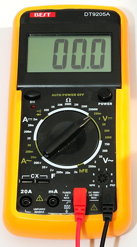
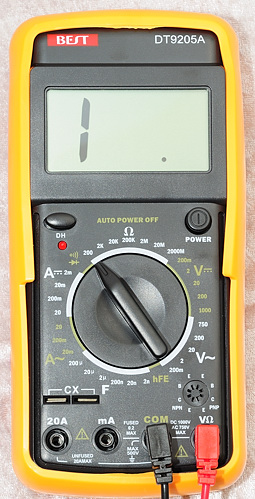
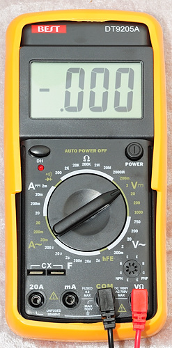
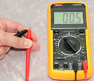
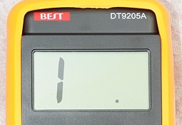
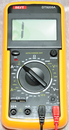
The cheap one is a "Best DT9205A" from DealExtreme, it has a maximum reading of 1999, range must be selected manually. It is usable for some measurements.
Note: Many cheap meters will measure wrong, without giving any warning, when the battery is nearly empty
I have included the following measurements in this guide:
- Current consumption: How to measure the tailcap current.
- Current consumption, using resistor: As above, but using a resistor instead of A range om meter.
- Current consumption: How to measure the tailcap current for high current draw lights.
- Power consumption: How to measure the power consumption.
- Tailcap switch: How to check a tailcap switch.
- Battery: How to check a battery.
- Battery tester: Using a battery tester.
- Testing an Incandescent Bulb: How to test a incandescent bulb.
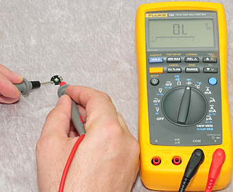
- Testing an led: How to test if a led works and polarity.
- Low ohmic measurement: How to measure small resistances.
- Charge current: How to measure charge current in a charger.
- Charge voltage: How to measure charge voltage in a charger.
In other articles/guides:
Current consumption
The current consumption can be used to estimate battery lifetime and power usage, it can also tell something about the driver in the light.
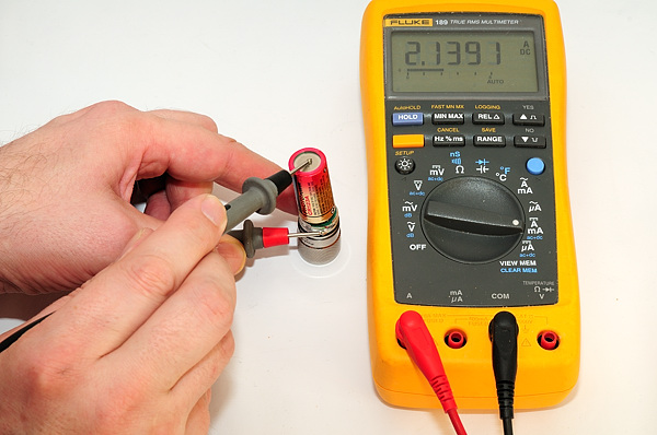
Select DC current measurement and move the plugs to the 10A/20A input terminal. For flashlight measurement it is best to select the highest current range, i.e. 10A or 20A range, this is done to keep the voltage drop in the meter as low as possible. For a multilevel flashlight on the lowest levels it can be necessary to use a more sensitive range, but this is only recommended if the reading can be keep below 1/10 of max. on the selected range. For lights that uses multiple amperes a clamp meter is better (see below).
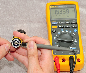
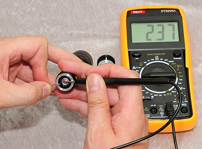
The tailcap is removed from the flashlight and the meter is substituted for that connection, i.e. one probe pin is placed on the battery and the other probe pin is placed on the battery tube, where there is some bare metal. Placing the probe pin on anodized metal will not work.
As can be seen, the two meters do not agree on the value. That is because the current draw is not really DC, but drawn in very fast pulses, the meters does not sum this the same way. This is only a problem on some flashlights.
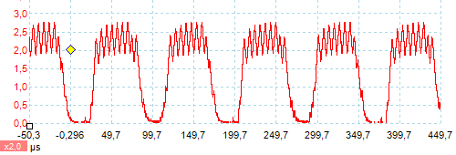
Using a oscilloscope and a current probe, it is possible to capture the actual current, it swings from nearly zero to about 2.7A. Letting the scope calculate on the waveform gives a value close to the Fluke meter.
Note: An oscilloscope is good at showing curves, but not very accurate when measuring
Current measurement can be used to estimate runtime and to reveal what kind of driver the lights is using, here are some measurement with NiHM batteries: Fully charged batteries: 1.35A, partial charged batteries (60% on ZTS): 1.78A, measured with the Fluke.
The current increases with declining voltage, i.e. the driver tries to keep the light output constant. And with eneloop batteries that has 2000mAh (2Ah) I would expect a runtime between 2/1.35 -> 1.5 hour and 2/1.8 -> 1.1 hour.
To calculate the power draw, the current must be multiplied with the battery voltage, as can be seen below it is about 1.2 volt under load and the light uses two batteries, the power is then (voltage*current): 1.2*2*1.6 -> 3.8 watt. Most of this power goes into the led where about 20% is converted to light, all the remaining power is converted to heat.
Note: See next chapter on how to measure the power, instead of estimating it.
Other types of light
Here are some examples on lights without tailcap.
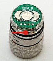
First example is a twisty, where the battery only makes connection when the light is twisted together. The battery tube is removed and the battery is hold in place with the fingers, the meter is used as a substitute for the battery tube connection and connected between battery minus and threads on the head.
In this example the tube and head is anodized, i.e. it is not possible to get a connection on the threads. It is necessary to make the connection at the same place as the battery tube touches the head, luckily there is enough space between the thread and the battery to get the probe down.
Current consumption, using resistor
Instead of using the A range on the meter, it is possible to use a resistor and measuring the voltage accross the resistor. This has some advantages and some disadvantages:
Advantage: Very good control with series resistance.
Advantage: It is simple to add a filter (Not shown here).
Disadvantage: Result must be calculated.
Disadvantage: Precision is depend on both meter and resistor.
Disadvantage: Wirewound resistor might add some inductance (This is usual not a problem).
When working with development it is also possible to solder all connections, to get better control with contact resistance.
On the meter the most sensitive DC voltage range must be selected (This depends on the resistor, but using a resistor that requires any other range it not a good idea).
The meter must be connected to a low ohmic resistor. This connection is not carrying any current and getting connection with ow contact resistance or low cable resistance from the resistor to the meter is not critical.
The meter connection and the connection to the flashlight must not be stacked, but must both be connected directly to the resistor leads.
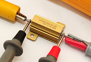
A 0.1 ohm resistor can be used, but a smaller value is better. The resistor must be able to carry at least the current that the flashlight uses. The power rating must also be large enough (any power resistor will usual be large enough, measuring 3 ampere only requires 0.1 ohm 1 watt).
Here I am using the leads on the resistor as connection to get as low resistance as possible. I could have soldered a (short) heavy gauge wire on the leds to get longer leads for connection, but it is not necessary here.
I measure 196 milli volt -> 0.196 volt, the resistor is 0.1 ohm and using ohms law I get voltage/resistance -> 0.196 / 0.1 -> 1.96 ampere. At the same time I know the voltage loss due to the resistor is at least 0.196 volt.
For measuring smaller currents a larger resistor can be used. A good selection of resistors for current measurements would be: 0.047 ohm, 0.47 ohm, 4.7 ohm. That would cover the range from below 5 mA to 4A with a voltage drop below 0.2 volt.
Notes
It is possible to make a low ohmic resistor from a piece of copper wire, but the value will change with temperature (Resistors are made of materials that changes very little with temperatur). Using nickel-chromium resistance wire (Nichrome) is much better and Constantan is best. Use the description in the "Low ohmic measurement" chapter to measure the resistance of the wire.
Current consumption: High current draw
When the current goes up, the precision on the DMM goes down, this is not because the DMM has a lower precision at high currents, but because the voltage drop over the probes and DMM will have more influence on the measurement. This is because we have to use the full range, not only 10% of the range and even a small resistance in the probes is significant at a couple of amperes when working with low voltage.
One solution is using a small resistor as shown above, another solution is using a current clamp meter.
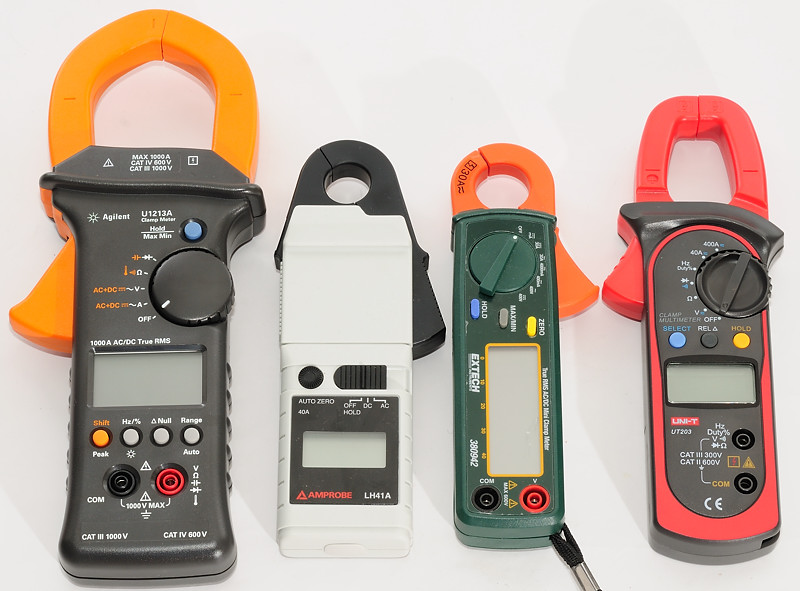
This picture show some very different clamp meters, what they all have in common is the ability to measure DC current (That is not present in all clamp meters).
- UNI-T This is the cheapest meters and has a resolution of 10 mA DC.
- Extech A medium quality meter, designed for low current measurement, resolution 1 mA DC.
- Amprobe A more expensive meter, also designed for low current measurement, resolution 1 mA DC.
- Agilent Top of the line meter, resolution 10 mA DC.
None of the meters are really useful at current below 0.1 A DC, they all work best at multiple amperes.
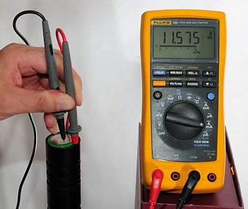
Back to flashlights and tailcap measurement, first a measurement with a DMM. This light is bad with 11.6 Ampere in tailcap current, can this be correct?
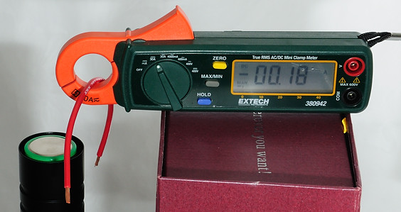
This looks strange, no current is flowing (wire is not connected) and the meter shows -0.18 Ampere. This is always the case with DC clamp meters, just rotate it a bit and it will change reading, because it changes direction in the Earth magnetic field. A clamp meter measures the magnetic field around the wire, but is also sensitive to other magnetic fields.
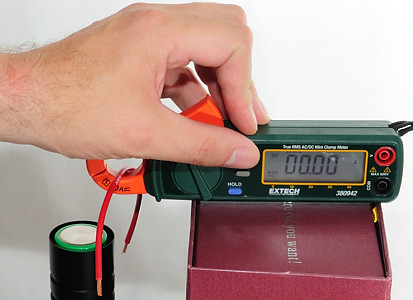
To handle this all DC clamp meters has a zero/rel/null button, press it and the meter shows 0. Remember to keep the meter in the same orientation after pressing the zero button. The meter might need some "warm up" time, before it can keep a stable 0 reading.
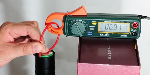
Doing the measurement with the clamp meter gives a much lower value, "only" 6.9 ampere. This is because the loss in probes and meter is much lower (The red wire is 2.5 mm2 or 13 AWG). Because this light is stabilized with a buck or boost converter it will draw less current at higher voltages (A direct drive light would draw more current).
Is this value the correct value? I will say it is close, but we do not really know at what voltage, because the batteries will not have the full voltage at 7 ampere current draw. Using the next setup will measure at what voltage the current draw is measured, but requires a more complicated setup and will have the voltage drop in the meter.
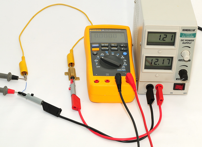
Power consumption
To measure the real power, it is required to measure both current and voltage at the same time. This is best done with two meters, but can also be done with one meter and low ohmic resistor. This description here is for two meters and measures the power to the flashlight, not the power drawn from the battery (The voltmeter must be moved to the battery side of the ammeter for that).
I will start with a drawing to show how the connections are done:
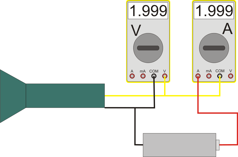
The voltage is measured with the meter closest to the flashlight, this way it is possible to compensate for the voltage drop in the ammeter. The current used by the voltmeter is much to small too affect the current measurement.
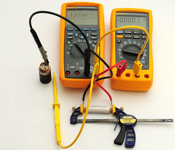
The first measurement is without connection to the flashlight, i.e. the current is 0 (Except for a small error on the meter).
The battery has an unloaded voltage of 1.277 volt, i.e. this battery has not recently been charged!
Note: Because the current is 0, the voltage is the correct battery voltage, there is no loss in the ammeter.
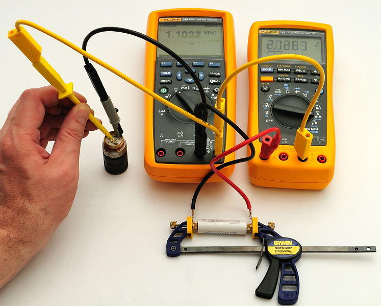
With the light connection the voltage is 1.102 volt and the current is 2.126 ampere, i.e. the power is voltage*current -> 1.102*2.126 -> 2.343 watt.
Probably 60% to 70% of this power will reach the led, i.e. around 1.5 watt (The efficiency is rather low, because the voltage has to be boosted to 3 times the input voltage).
Nearly all the power will be converted to heat in the light, except the 20% of the led power that comes out the front as light. That is about 0.3 watt of light.
Note: A fully regulated light will draw close to the same amount of power, independed of the battery voltage, but most 1.5 volt lights are not fully regulated.
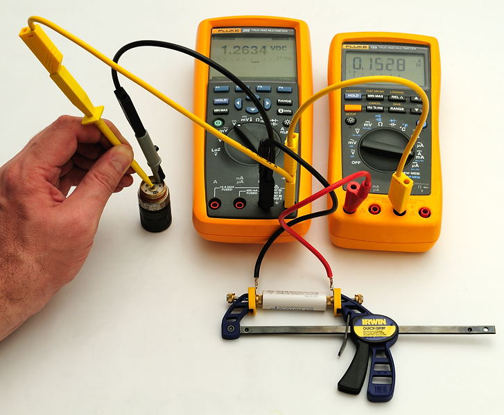
Selecting a lower level on the light, will reduce current and battery voltage will go up, both because the battery has higher voltage at lower load and because the voltage drop in the ammeter is smaller.
The result is voltage is 1.263 volt and current is 0.153 ampere, this gives 0.193 watt
Notes
This method requires that the ammeter measures correct, with some meters this can be a problem on some lights (See chapter "Current consumption" above)
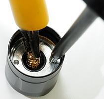
Tailcap switch
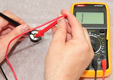
It is easy to check if the tailcap works with a multimeter.
For this measurement the lowest ohm range must be selected. The Fluke with autorange will select the highest ohm range, but will automatic change to the lowest range when measuring.
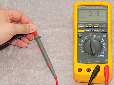
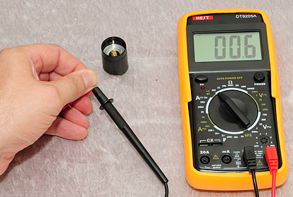
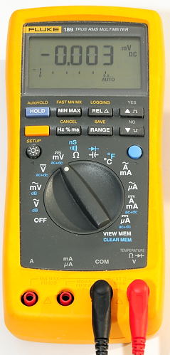
Before doing any low ohm measurement, it is a good idea to check the meter to see what the lowest value it can show is. The Fluke shows 0.13 and I could have changed that to zero by pressing then "REL" button. The other meter shows 0.6. I.e. anything close to these values can be assumed to be about zero. To get more exact result at these low values, other methods must be used.
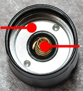
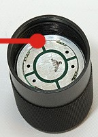
One probe pin is placed on the center spring, the other probe pin is placed on the metal connected to the tailcap. The red circle shows the place.
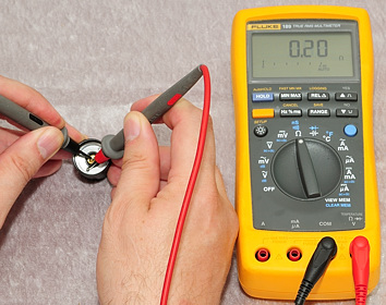
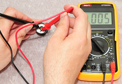
Both meters gives a reading very close to the reading with shorted pins, i.e. the switch/tailcap has a low resistance and is on.
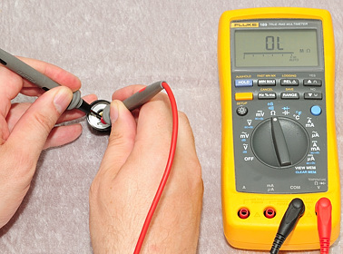
Here the switch is off, or the tailcap/switch is not working correctly.
Some two level lights does have a resistor in the tailcap, this resistance is activated at the low level, expect a resistance in the range 10-100 ohm. A few multi level lights has an electronic tailcap, this makes it impossible to do a valid resistance measurement.
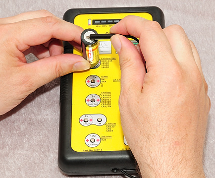
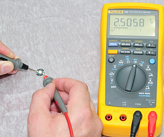
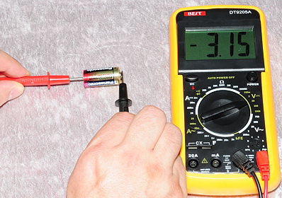
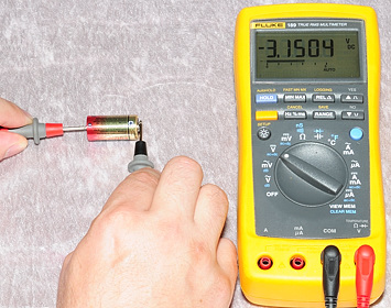
Battery
The measurements on a battery depends on the chemistry in the battery, I have examples with alkaline and LiIon here.
The DC voltage range must be selected and depending on battery chemistry either the 2V or 20V range must be used. Autoranging meters will select the correct range automatically.
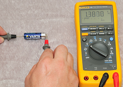
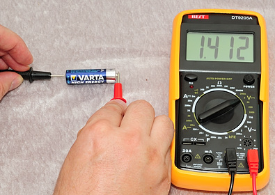
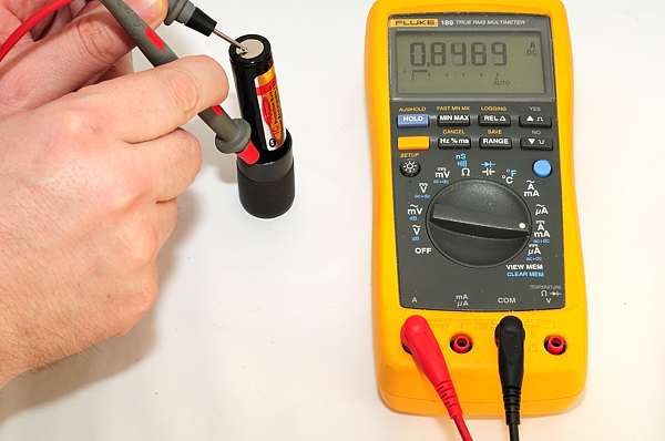
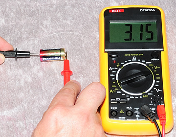
First measurement is on a alkaline battery, this requires the 2V range, it has about 1.4V, but the measurement does not really say anything about how much energy that is left in the battery, only that it still contains some energy. The reason for the difference between the two meters is because I did the following tests, before I measured with the Fluke meter and did not give the battery enough time to recover.
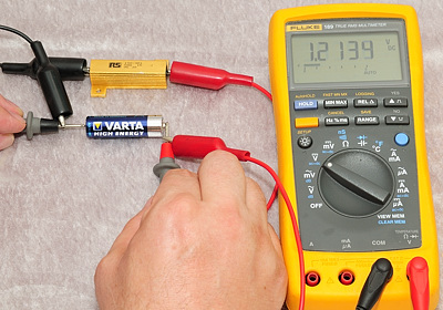
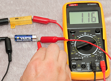
To get a better idea about how it will work in a flashlight, I need a load on the battery, here I am using a 1ohm resistor. The battery still maintains voltage enough to drive a flashlight. The resistor must be at least 3 watt, but a resistor rated for a higher wattage (i.e. 10 watt) is much better, because it will stay cool.
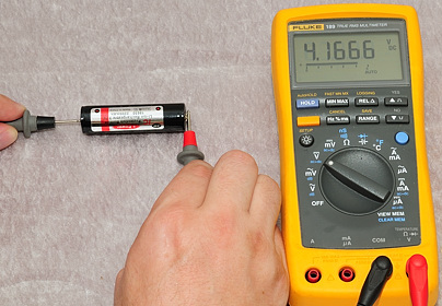
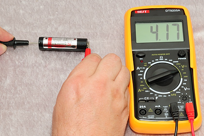
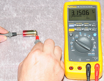
Next battery is a LiIon 18650 battery, this requires the 20V range, the battery has 4.17 volt. For a LiIon this means that it just about fully charged. The voltages for a LiIon must be measured without load and are: Fully charged 4.2V, empty 3.6V
When getting a new LiIon charger it can be a good idea to check the voltage, on the cells, when they are removed from the charger, they must not be above 4.3V, it is much better if they are at 4.2V.
Battery tester
When measuring batteries, it is much easier with a real battery tester, it has a build in table of the different voltages and chemistries and can use a build in resistor to load the battery when needed.
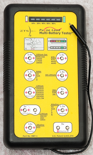
The ZTS is one of the good battery testers, this model here has support for most of the batteries used in flashlights.
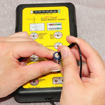
It is very easy to measure all chemistries and get an estimate of remaining power. The meter says 80% for the alkaline and 100% for the LiIon battery.
Testing an Incandescent Bulb
Usual it is possible to see if a bulb is burned out, but it can also be tested with a multimeter.
For low voltages bulbs the lowest ohm range is fine.
Before doing any low ohm measurement, it is a good idea to check the meter to see what the lowest value it can show is. The Fluke shows 0.13 and I could have changed that to zero by pressing then "REL" button. The other meter shows 0.5. I.e. anything close to these values can be assumed to be about zero. To get more exact result at these low values, other methods must be used.
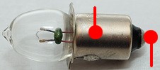
The probe pins must be place at the two connections on the bulb and they must not touch each other (Can be difficult on the small bulb).
These bulbs's has a low value and it is difficult to measure exact, one problem is the connection from the probe pin to the bulb, it can be difficult to get a connection with low resistance. Luckily there is no need for exact measurement, as long as the meters show a value, the bulbs works. The measured ohms can not be used to calculate the current in the bulb, when power is connected the temperature will rise more than 2000 degrees and the resistance will increase considerable.
Display for a blown bulb.
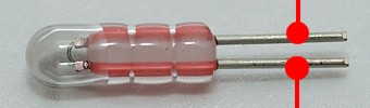
Testing an led
This is a measurement/test not all multimeters can do, some are missing the range and others are not designed for measuring leds. When the meter can do it, this is an easy way to check if a led works and the polarity of the led.
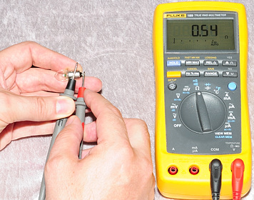
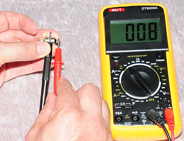
Select the diode range, on some meters this is a shared position on the selection switch and a button must be pressed to select the diode range (On the Fluke I must press the round blue button once).
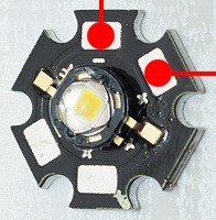
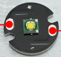
To test a diode/led the red probe pin must be connected to + and the black probe pin must be connected to -, this is easy when it is marked on the diode mounting plate, but when marking is missing, it is possible to try until the correct connections are found (The meter will not damage the led). The correct connection (i.e. the connection where the led lights up) is the same connection that must be used when mounting the led.
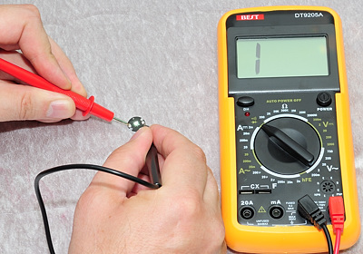
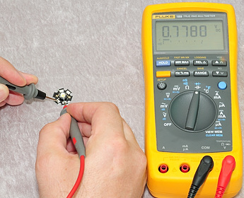
The Fluke meter has no problem testing a led, it shows the voltage over the led and the led is lit. The BEST meter can not show any value, but the test is not completely useless, because the led will glow, when the probe pins are connected correctly.
The voltage shown will depend on the color of the led and the measurement current the meter uses.
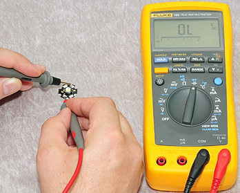
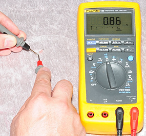
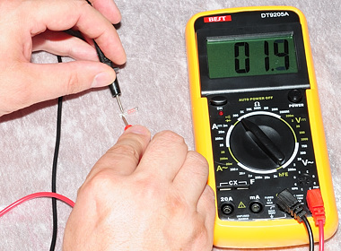
There are a lot of possibilities for wrong connections, or defect leds. In the first picture I have connected the probe pins the wrong way around and there is no connection (This is typical for a diode). In the second picture, I have also connected the wrong way around, but this led has a protection diode and there is not an open connection, but instead a low voltage.
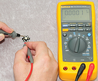
Here I have connected the meter to two connected pads and it shows 0 volts and in the last picture I simulate a broken connected.
Low ohmic measurement
There are many ways to do a low ohmic measurement, the simplest is to buy a 4 terminal ohmmeter, but here I will show how it is done with a voltmeter, a power resistor, a power supply and a little bit of mathematic with ohms law.
Here is the equipment. The power supply must be stabilized supply that can supply between 10 and 15 volt with at least 1.5 ampere. The resistor is a 10 ohm 1% power resistor, I am using a 25 watt resistor (Using a 50 watt would be better).
In the above picture I am measuring the resistance of a piece of blue wire.
To do that I make a circuit from the power supply through the 10 ohm resistor and through the blue wire.
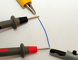
When I have made the circuit I turn on the power supply and measure the voltage across the 10 ohm resistor and the voltage across the blue wire. When doing these measurement it is very important how I have placed the connection to the power supply and how I have placed the connection to the meter. The measurement probes must not touch the power supply connection.
When I have done the measurements I turn the power supply off again, to avoid heating the resistor.
The measurement I got from the above was:
10 ohm (reference) resistor: 12.067 volt
Blue wire: 0.0077 volt
Now I have to do the following calculation: voltage_over_test_object*reference_resistor/voltage_over_reference_resistor
With numbers: 0.0077*10/12.067 -> 0.0064 ohm or 6.4 mOhm
I.e. the short piece of wire has 6.4 mOhm.
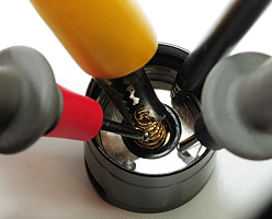
Next up is a tailcap, first picture shows connection to power supply and resistor, in the second picture I have also added the meter probes. Again it is important that the power supply connection and the meter probes do not touch each other, but only touches part of the tailcap.
The measurement I got from the above was:
10 ohm (reference) resistor: 11.92 volt
Tailcap: 0.047 volt
With numbers: 0.047*10/11.92 -> 0.0394 ohm or 34.4 mOhm
I.e. this tailcap has a on resistance of 34 mOhm
Notes

Here is an example how not to do it, the measurement probes touches the connection to the power supply. This means that the result will include the connection resistance between the alligator clip and the resistor.
The precision of the above ohmic measurements are very depend on the precision of the 10 ohm resistor and a stable voltage from the power supply, all other errors will mostly cancel each other out.
If I adjust the power supply to deliver exactly 1 ampere, the voltmeter will directly show the resistance in ohms (milli volt is milli ohm) when measuring across the test object, there is no reason to measure across the 10 ohm resistor.
Charge current
Not all chargers are completely thruthful with the charge current, with a multimeter it is possible to check the current. There are many possibilities for connecting the meter, I will show one where the battery stays in the charger. This example will be with the WF-139 charger and a LiIon battery, but this methode can be used on most charges, both for LiIon and for NiMH batteries.
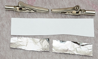
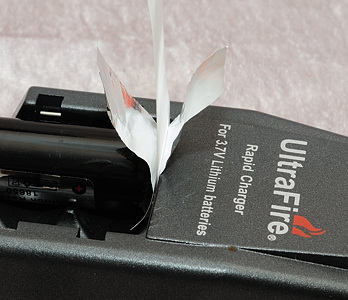
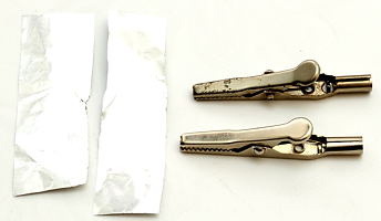
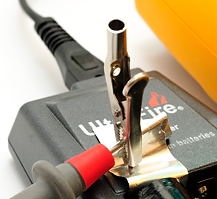
First we need some equipment, two pieces of tinfoil, a piece of paper and two alligator clips (Other clips can also be used).
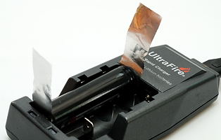
This must be mounted on the charger, together with the battery. This is best done before power is connected to the charger and check that the tinfoil does not touch any metal, except the battery pole and the charger pole, it must not touch the nearby charger poles or make a short from the battery + pole to any other metal on the battery. It can be mounted at either the + or the - pole on the charger.
Select DC current measurement and move the plugs to the 10A/20A input terminal. For measurement it is best to select the highest current range, i.e. 10A or 20A range, this is done to keep the voltage drop in the meter as low as possible. For small batteries and low charge current it can be necessary to use a more sensitive range, but this is only recommended if the reading can be keep below 1/10 of max. on the selected range.
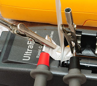
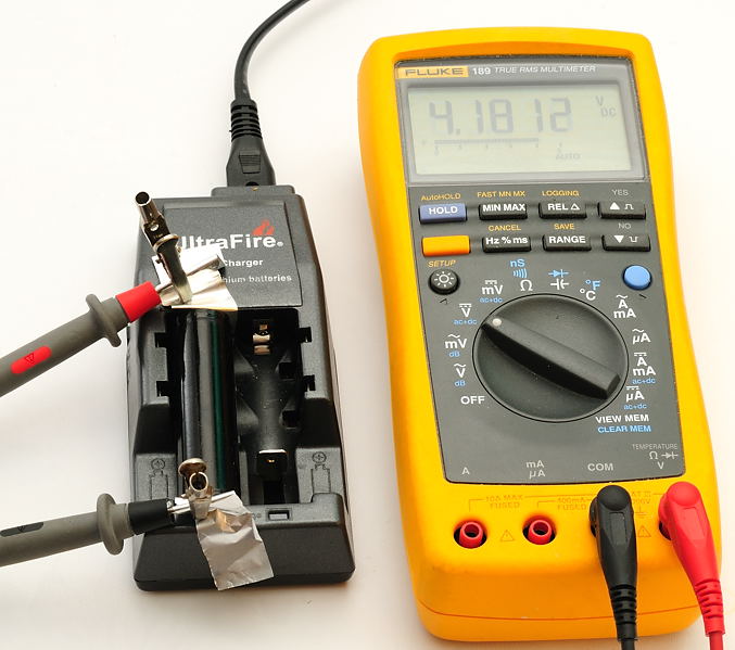
Connect the meter to the tinfoil, using the alligator clips to secure the probes. Connecting the probes this way will secure a low impedance and a low voltage drop, i.e. confusing the charger as little as possible.
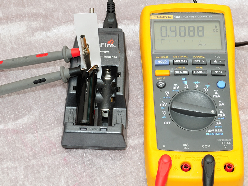
Here is the final result, with a charge current a bit above 400mA, but not as high as the rating on the charger (it is 450mA). The lower current might be because the battery is nearly full.
Note: Some meters will automatic turn off after some time, this will not interrupt the charge. To make more readings, turn the meter on again.
Charge voltage
If you want to see how a charger is filling the battery, it might be interesting to measure charge voltage. I will shown an example with WF-134 charge and a LiIon battery, where the battery stays in the charger.
To get access to the poles on the charger two pieces of tinfoil and two alligator clips are used. The tinfoil is placed between the charger poles and the battery poles. This is best done before power is connected to the charger and check that the tinfoil does not touch any metal, except the battery pole and the charger pole, it must not touch the nearby charger poles or make a short from the battery pole to any other metal on the battery.
Next the meter must be connect, wrap the tinfoil around the probes and secure with an alligator clip.
Turn the charger on and watch how the battery/charger voltage will rise. With a logging meter or a meter connected to a PC it is possible to record a curve.
Note: LiIon will rise to about 4.2 volt and stay there for some time, before the charge is finished. NiMH will rise to somewhere between 1.5 volt and 1.6 volt and then drop a few milli volt signaling that they are fully charged (This is called dv/dt).
Notes
A multimeter needs two connections to measure, one is usual with a red probe and the other with a black probe. By convention the black probe is connected to the COM terminal and the red probe is moved between the other terminals. When connecting the probes to the object to measure, it is not necessary to connect the red probe to + and the black probe to -, either way will do. If the red probe is more negative than the black probe, the display will show a minus sign before the result. The only exception to this is the diode range.
When finished with the meter it is a good idea to never leave the probes in the 10A/20A terminals. If the probes are connected to the meter, leave them in the COM and V/OHM terminals.
The reason for this is safety, if someone connects the meter to a mains output, the meter might explode if the probes is in the 10A/20A hole.